
Validating an Automotive Console Injection Mold Before Production
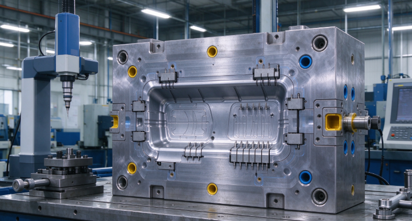
The first molded console sample is a milestone, not the end of tooling validation. Production readiness depends on repeatable process conditions, dimensional conformity, appearance, assembly fit, and documented approval. Hisured Mold Tech lists an automotive console mold and a typical 35–65 day lead-time range that varies by drawing, material, tool structure, and validation [1]. This guide lays out practical validation gates for buyers and program teams, while keeping acceptance criteria tied to the vehicle customer’s drawings and quality plan.
Agree on what each sample stage proves
Before trials begin, name the sample stages and the evidence required at each one. An early trial can confirm that the mold opens, fills, cools, and ejects. It does not necessarily prove final dimensions, cosmetic quality, cycle time, or process capability. State the press, resin grade and lot, color, machine settings to record, sample quantity, and whether parts will be conditioned before inspection. Label every sample with tool number, cavity, date, resin batch, and trial conditions.
Separate tooling correction from product design change. A short shot caused by venting differs from an undersized feature caused by a design revision or material shrinkage. Maintain a change log with issue, root cause, responsible party, proposed action, approval, and re-trial requirement. This prevents repeated changes from obscuring whether the mold or the product definition is being corrected.
Measure critical dimensions with a repeatable method
Create a ballooned drawing or inspection plan that links every critical dimension to a datum, method, sample quantity, and acceptance limit. Console geometry can be large and flexible, so support conditions matter. Agree whether the part is measured free-state, in a fixture, or assembled to mating components. Record measurement equipment, calibration status, and environmental or conditioning conditions when they affect results. A coordinate-measuring machine report is useful for geometry, but it does not replace fit and functional checks.
ISO 20457:2026 addresses geometrical and dimensional tolerances and acceptance conditions for plastic molded parts [2]. It recognizes that molded plastics behave differently from metal parts and that achievable tolerances depend on material and process. Use it to guide conversations about tolerance class and measurement, not to retrofit generic limits onto the customer drawing. The design owner should designate which dimensions control mounting, retention, sealing, gaps, flushness, or interfaces with nearby components.
Evaluate appearance and console assembly
Define visual inspection conditions: lighting, distance, viewing angle, surface zone, texture master, gloss range if specified, color standard, and allowable defects. Review gate vestige, flow lines, weld lines, sink, blush, scratches, flash, and ejector marks against the program’s criteria. A verbal description such as “automotive appearance” leaves too much room for disagreement. Use approved samples, limit samples, or a written defect catalog when the customer requires them.
Assemble the molded part to the console structure and adjacent trim. Test clips, screws, hinges, storage-bin lids, cup-holder inserts, electrical switches, and harness routing as applicable to the actual design. Check retention force, rattle, gaps, flushness, and interference using the customer’s procedure. A standalone dimensional pass can still miss an assembly stack-up. Record the mating part revisions and assembly conditions so a later design change does not invalidate the result silently.
Use a risk-based process and durability plan
Select validation tests based on the part’s function, material, environment, and customer requirements. Risks may include thermal deformation, creep under sustained loading, impact, chemical exposure, vibration-related noise, clip fatigue, or stress cracking. The supplier should not invent pass limits: the OEM or design authority defines test conditions and acceptance criteria. Confirm whether the trial resin is production-equivalent, whether colorants or regrind affect properties, and whether tests require conditioned samples.
For automotive program control, the customer may request APQP, PPAP, control-plan, or process-change documentation. AIAG’s APQP 3rd Edition was released in 2024 and includes updates covering sourcing, change management, program metrics, and risk assessment [3]. The buyer should identify the required manual edition and deliverables. A toolmaker’s participation in a program does not imply that the company is certified or that all customer-specific approvals are complete; request the exact evidence required by the customer.
Close the loop with approval and handover
At final approval, confirm the accepted part revision, resin, color, cavity identification, process window, inspection report, and unresolved deviations. Define tool maintenance intervals from supplier recommendations and customer production needs. Request a spare-parts list, maintenance history, cooling circuit diagram, electrical and hydraulic interface details, and tool lifting information if required. Establish who owns the mold and who may authorize modification or transfer.
A production handover should include signed approvals, final samples, dimensional and appearance records, approved process settings, tool and part identification, and a clear change-control route. If production transfers to another facility, run a receiving trial and verify fit, quality, and process before authorizing serial shipments. The tool remains a controlled asset throughout its service life; changes to resin, press, cooling, or process settings can affect dimensions and appearance and should be reviewed under the agreed control plan.
Validation gates and measurable evidence
The gate sequence below is a project-planning template. Sample quantities and acceptance limits must be set by the OEM or customer, not assumed from a generic guide.
Gate | Evidence to agree | Numeric / published context |
Design freeze | Released model, drawing, material and press interface | Hisured estimate: about 35–65 days, project dependent |
Initial trial | Fill/ejection review, trial log, labeled samples | Record press, resin lot and cavity identity |
Dimensional and fit review | Ballooned report and assembly trial | Use drawing limits; ISO 20457:2026 is a tolerance reference |
Production approval | Customer-required quality package and change control | AIAG APQP 3rd Edition published 2024, if required |
Tool handover | Ownership, maintenance, spare parts and records | Confirm scope in the purchase order |
Frequently Asked Questions
Is a T1 sample the same as production approval?
No. It is a trial stage. Production approval requires the specific dimensions, appearance, assembly, process, and customer documentation defined by the program.
Should appearance be judged from photographs?
Photographs help record defects but should not replace an agreed physical inspection condition and approved visual standard.
Who sets the acceptable tolerance?
The product drawing and customer requirement define actual limits; standards can provide guidance but do not approve a particular part.
Conclusion
A robust validation sequence establishes what each trial proves, uses repeatable dimensional and visual methods, checks the console in assembly, and closes deviations through the proper design authority. Treat the published lead-time range as a planning input and reserve time for customer reviews and corrections. Complete handover records make the mold easier to maintain and transfer into stable production.