
How to Specify an Automotive Console Injection Mold
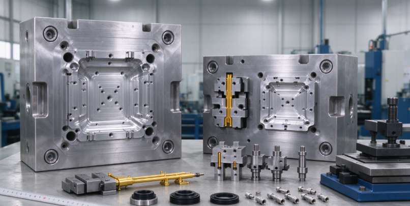
An automotive console injection mold is a production tool designed around a specific interior component, resin, press, cosmetic standard, and launch plan. Console parts can combine visible Class-A surfaces, clips, fasteners, storage features, ducting, and interfaces to adjacent trim. A mold quotation is useful only when these requirements are clear. Hisured Mold Tech lists an automotive console injection mold and publishes an indicative mold lead time of approximately 35–65 days, subject to drawing, material, mold structure, and validation requirements [1]. This guide explains what a buyer should define before the schedule begins.
Define the part, application, and cosmetic zones
Start with the latest released 3D model and 2D drawing, including all revisions, datums, tolerances, and GD&T. Identify which surfaces are visible to occupants, which are hidden, and which are functional interfaces. Console parts may include cup-holder openings, storage-bin interfaces, switch apertures, fastener towers, clips, hinges, or console-to-instrument-panel transitions. Mark these features and state acceptable flash, sink, mismatch, texture, gloss, color, and gate vestige requirements using the vehicle program’s approved criteria.
Clarify whether the tool produces one component or a family of related parts, whether left- and right-hand variants share tooling, and what annual volume and service life are expected. Define the target press, tie-bar spacing, platen limits, shot capacity, mold height, opening stroke, ejector interface, and robot or operator handling. Without press data, a tool may be technically manufacturable but incompatible with the intended production line. If the press has not been selected, include the range of candidate machines and identify who will approve the final interface.
Make the tool concept match the part design
The mold review should cover parting line, draft, wall transitions, ribs, bosses, undercuts, slides or lifters, ejection, venting, and gate location. A large trim panel may need careful warpage management, while a deep storage feature can complicate cooling and ejection. The toolmaker should flag geometry that risks sink, weld lines, trapped air, stress, or visible flow marks and propose changes for the customer’s design authority to approve. A DFM review is most useful before steel is cut, not after a first sample reveals an avoidable issue.
Specify the required cavity count, hot-runner or cold-runner preference, gate type, tool steel or hardness where customer standards dictate it, expected maintenance access, and spare inserts. These details depend on cycle target, resin, annual demand, cosmetic sensitivity, and tool-life expectations. A supplier may recommend an alternative, but the proposal should state the tradeoff in cost, maintenance, yield, and schedule. Do not accept a cavity or steel choice based only on a generic supplier claim.
Control material and dimensional tolerances
Name the resin by customer-approved grade, supplier, color, reinforcement, and any recycled-content requirement. “Automotive plastic” is not a material specification. Resin flow, shrinkage, fiber orientation, moisture, and processing window affect dimensions and surface appearance. Confirm whether the customer will supply resin or approve an equivalent. Define the conditioning and measurement state for critical dimensions so that supplier and customer inspect samples consistently.
ISO 20457:2026 is the current second edition for geometrical and dimensional tolerances and acceptance conditions for plastics moulded parts, with guidance on technically achievable tolerances [2]. It also explains why tolerances for metal parts cannot simply be transferred to plastics. Use it as a discussion reference where appropriate, then place the actual critical-to-function dimensions and acceptance limits on the drawing. The standard is not proof that a particular tool or molded part complies, and it does not replace OEM-specific requirements.
Plan sampling and validation before ordering steel
Agree on the sampling stages, sample quantity, resin lot, press, process window, and inspection report before tool kick-off. A T0 or T1 sample may demonstrate mold operation but does not automatically meet production quality. Define who reviews the first article, how dimensional results are reported, which surfaces are judged visually, and how open issues are classified. Include assembly trials with mating parts where clips, fasteners, hinges, or adjoining trim influence fit.
Create a risk-based validation plan for short shots, flash, sink, warpage, color mismatch, weld-line weakness, ejection marks, and dimensional drift. The exact tests and limits should come from the vehicle program. If automotive launch documentation is required, identify the customer’s APQP, PPAP, control-plan, and change-control expectations. AIAG published APQP 3rd Edition in 2024 with expanded focus on sourcing, change management, metrics, and risk assessment [3]. Hisured’s public pages do not establish a company certification or a customer-specific approval; ask for applicable evidence directly.
Review schedule, ownership, and deliverables
Hisured states an approximate 35–65 day mold lead time and notes that timing varies with drawing, material, mold structure, and validation [1]. Treat this as a planning estimate rather than a contractual commitment. Confirm when the clock starts, whether DFM approval and steel procurement are included, how many sample loops are assumed, and how customer review delays affect delivery. Ask for a milestone plan covering design review, tool design approval, steel procurement, machining, assembly, trial, correction, and shipment.
The purchase order should state tool ownership, storage, maintenance, spare parts, export packaging, delivery term, and what happens if the program is paused. Define the CAD formats, drawing package, inspection data, sample labels, and change log required at handover. If the mold will run at another molder, include the receiving press information and transfer validation scope. Confirm whether the quoted price includes resin for sampling, texture, hot-runner controls, spare inserts, and any fixture or gauge needed for acceptance.
Published and standards-based planning data
The lead-time range is published by the supplier and is explicitly dependent on project conditions. Standards below are references, not claims of supplier certification.
Item | Data | Use in project planning |
Hisured product catalog | 11 products across 5 categories | Company-listed range; verify the current product page. |
Published mold lead-time estimate | Approximately 35–65 days | Confirm start event, assumptions, sampling loops and delivery term. |
Molded-part tolerance reference | ISO 20457:2026, second edition | Discuss plastic part tolerances; drawing limits remain controlling. |
Automotive planning reference | AIAG APQP, 3rd Edition (2024) | Use only if customer program requires this planning framework. |
Frequently Asked Questions
Does 35–65 days guarantee mold delivery?
No. Hisured describes it as an approximate lead time dependent on drawing, material, mold structure, and validation. Confirm a project schedule in writing.
Can ISO 20457 assign every console tolerance?
No. It provides general tolerance and acceptance guidance for molded parts. The drawing and customer specification set the actual limits.
Does a mold quotation include production-part validation?
Not automatically. State sample quantities, inspection, assembly tests, and launch documentation in the RFQ.
Conclusion
A console mold is a custom production system whose cost and schedule depend on the released part, material, press, cosmetic criteria, tooling concept, and validation plan. Hisured’s published 35–65 day estimate is a useful starting point, not a commitment without scope. A complete RFQ and early DFM review help the customer and toolmaker resolve key risks before steel release.